
Available to buy now!
TLDR: We’ve reached design lock, production parts have been ordered and we aim to start shipping the first batch of machines in late July.
Let us just begin by saying that production parts are on order, we’ve finally reached design lock and hit the button! This may have taken a little while but we are so excited and proud of this machine and cannot wait to start shipping them out into the wild.
Now you’ve probably got a vision of us all sat around with our feet up, sipping on our tea waiting for these parts to arrive. Think again, we’re busy finalising our new ToolChanger assembly line and we’re really pleased with how it's shaping up (pictures pending)! So, without further ado let us get you up to speed with the final changes we've made to the machine...

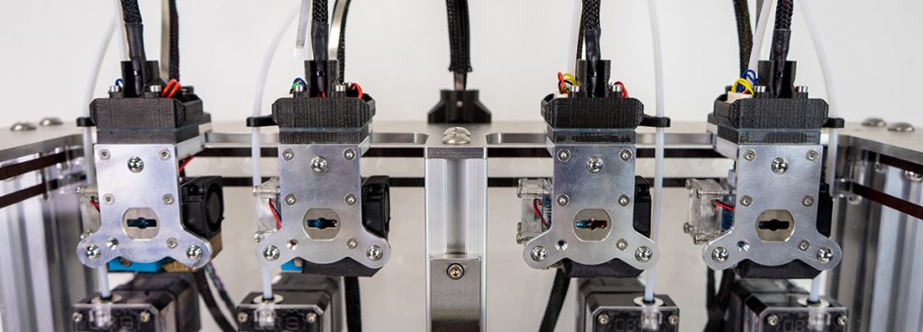
 The E3D Motion System and ToolChanger
Servo vs Stepper Motor
We’ve swapped out the Servo for a Stepper Motor and by doing so have seen ridiculous results… The old Servo was struggling to exceed 60,000 tool changes whereas the new beastly Stepper Motor can easily surpass 400,000 cycles. Once we reached the 400,000 cycle mark we took the motor apart to check for wear. Which, after a thorough inspection, turns out was non existent! Another benefit of swapping the two? The Stepper Motor is totally silent. Overall, this decision makes it far easier and convenient to control as it’s simply another axis connected to the Duex5 expansion board.

 *Please note that the motor bracket will be machined from Aluminium*
Say Goodbye to the Carbon Fibre Bar
The stiffer the better, right? We’ve said goodbye to the carbon fibre bar and replaced it with fancy machined aluminum and oh boy have we’ve seen a drastic increase in stiffness; in fact it’s now twice as flexurally stiff and 3 times more torsionally stiff. In doing so we’ve only increased the total flying mass by a couple of percent and the machine can now carry the tools with far less pressure, win win! Additionally, it solves the issue with the differences in the coefficient of thermal expansion between carbon fibre and steel. The carbon fibre bar expanded at a very different rate to the Hiwin Rails and consequently we were seeing bending that caused issues with calibration and bed leveling; this has now been eliminated. Oh and just quickly on the topic of stiffness, your Motion System will now come with clear acrylic side panels!

 *NEW* machined aluminium bar

 More machined beauty for you to feast your eyes on
The first ToolChanger to land on the Moon…
The final significant change that we’ve made is to replace the original motors with Moons motors. There’s now much lower inductance which means that we can accelerate and move significantly faster, resulting in fewer skipped steps and ultimately gaining more reliability.

 *NEW* Moons' Motors
Wear Testing
At this point it’s important for us to stress that the machine has undergone accelerated wear life testing (thousands of cycles) on the ToolChanger mechanism and has held up superbly well. The only component that we’ve seen wear after all of these cycles is the pin, this is due to the fact that it’s made from a softer metal which prevents it rubbing any metal away and luckily for you guys is mega cheap (we’re talking pennies) and quick to replace.
The ToolChanger is available to buy now!
Remember to check out our Beta Testers' #ToolChanger journeys:
Twitter:
Brendon - @brendonbuilds
Elliot - @egriffiths94
Rich -@RichRap3D
Scott - @thinkyhead
Tony - @kraegar
Loubie - @loubie3D
YouTube:
Tony Akens - https://www.youtube.com/channel/UCEy0ddxRt61cTmJZv_ZvXgg
René Jurack - https://www.youtube.com/watch?v=sd941kne_z8&t=2s
Instagram:
Joe - @nemesis.robotics
Nikolai - @nikolai.py
Blogs:
Mike Hackney - https://www.sublimelayers.com/search/label/Tool%20Changer?&max-results=8
Ivor O'Shea Blog - https://ivoroshea.blogspot.com/
Rich Horne - https://richrap.blogspot.com/
ToolChanging 3D printers - https://www.facebook.com/groups/237615240416855/?ref=br_rs