
It's been a long road to v6; we've gone back to the drawing board and taken a good hard look at every tiny detail in the system. We've had to push back release a few times to ensure that things were absolutely correct in manufacture and design, but we're finally ready to release the full details of our new HotEnd.
The v5 HotEnd has a great track record of excellent performance and has gained a solid community following since its release last year. However nothing is perfect and from community feedback, comments from our partners who integrate v5 into their printers and our own experiences we identified some key areas we thought could be perfected.

Design Criteria
-
Decrease bulk.
- v5 is longer in the Z axis than many other HotEnds on the market due to significant safety margins in heat dissipation, and screw-in Bowden fittings make Bowden HotEnds even longer.
- Our printed fan duct is a little bulky in X/Y which can create issues when space under carriages is restricted.
-
Make assembly and maintenance easier for the user.
- Securing thermistors with Kapton tape works well, but is difficult to achieve easily and neatly, especially for the new user. It also makes changing out thermistors a bit time consuming. Cementing in thermistors with fire cement or similar works well, but is messy and difficult, and also makes changing thermistors nearly impossible.
- The printed fan duct is a bit tricky to remove as it has to be slid off the heatsink either up or down, which can be tricky with wiring etc in the picture.
-
Improve support for flexible materials.
- v5 works as well as any other HotEnd on the market for flexible filaments, however this inevitably means printing very slowly, getting messy prints and having to constantly battle with buckling in the extruder.
- Flexible filaments are entering the market and have some exceptionally useful properties and we want to enable more people to use them with a better printing experience.
-
Shorten heat up times and increase accurate control of temperature.
- v5 uses a set screw to secure the cartridge which works well, but because of the slight variances in heater cartridges the hole in which the cartridge sits has to have some clearance to allow it to easily slide into place, this affects heat up times and control.
- Thermistor placement in v5 is close to the surface of the block, which makes things easier when your thermistor has to be insulated with kapton but has some impact on the precision of the readings.
-
Fix niggling reliability issues.
- v5 has a great track record of reliability with less than one per cent of users experiencing issues due to manufacturing, however we really wanted to eliminate any chance of future defects.
- 1.75mm Bowden users were experiencing a disproportionate amount of problems, which was traced back (with much help and hard work from Michael Hackney) to nozzle geometry in certain situations needing high extrusion pressures that resulted in starvation of filament flow.
-
Make different sized nozzles more suitable for their application and each size more identifiable.
- All v5 nozzles share the same shape of tip that lays down the track of filament, we wanted to make the shape of each nozzle more suited to their particular use case and application so people can get the best results from each nozzle size.
- Because all nozzles share the same shape they are hard to tell apart, particularly when there is plastic residue remaining on the nozzle. We wanted to make it easy to differentiate between nozzles.
-
Make it beautiful.
- Looks matter! Our machined metal parts look awesome, but with them hidden behind a printed fan duct you can't admire all that wonderful engineering.
Here's what we came up with

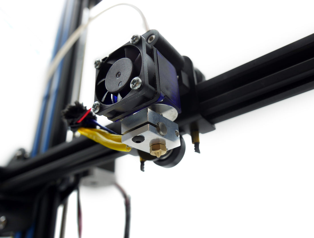
Decreasing size
Our first mission was to decrease bulk - the heatsink and the fan comprise much of the size of the hotend, with bowden fittings in the relevant versions also adding a fair bit of size up top.
The first target for slashing size was the heatsink. We've moved to a smaller diameter heatsink that is also shorter in length. By switching to a very thin cutting tool we were able to get more fins in less space and so retain sufficient surface area on the heatsink to still get good cooling out of a smaller heat sink. It's also 30% lighter than the previous heatsink.
The next vector for reduction in size was the fan duct. After much agonising over the merits of printed parts and the cost of tooling up for injection moulding, we went for an injection moulded part.
The new ducts are a great deal thinner and less bulky in all directions than the previous printed versions. We had these done in polycarbonate resin too which makes them ultra tough and resistant to temperature extremes.
The next area to address was the Bowden couplers - we consulted with a specialist in tube coupling solutions and took inspiration from how similar things are achieved in the pneumatics industry. We managed to come across a solution so small that it would fit entirely inside of the HotEnd! The coupling system we're using is exactly like the screw-in fittings we're all used to, where a collet holds the tube in place and the tubing can be released easily by simultaneously pushing in the collet and pulling out the tube, just a great deal smaller in size.

For the 3mm versions the integrated couplers were a tiny bit bigger which meant that we had to deviate from our previous groovemount dimensions slightly, but because the previous coupler sat in that space anyway it shouldn't make much difference in terms of mounting considerations.
A Convenient Side Effect
Because the new Bowden coupling system sits entirely within the HotEnd this now means that there is no need for 2 separate 1.75mm products for Bowden and Direct users. Instead we have a 1.75mm Universal product that has the internal couplers installed. Direct users just need a short length of tubing to line the filament down into the HotEnd, and Bowden users can simply use a longer piece of tubing with a coupler to fix the other end to their extruder.
Making it Easier
Kapton is an amazing space-age material that has paved the way for innovations in electronics, aerospace and many other areas in our modern lives. It's also a total pain in the arse. When done well it works perfectly functionally, it's just not as clean or easy a process as we would like.
Here we present a somewhat more elegant solution using small diameter glass fibre sleeving and a clamping screw.

To deal with the inconvenience of having to remove the fan duct by sliding it either up or down off the heatsink we have designed the new injection moulded duct so that it simply clips into place over the heatsink from the side, with a satisfying snap as it does so.
Improving Performance for Flexible Filaments.
Flexible filaments are amazing and open up a huge range of possibilities for new practical applications in 3D printing, and they're also just plain fun. However printing them can be really hard work, especially in 1.75mm where the lower diameter of the filament results in a filament that has mechanical properties similar to that of a wet noodle. To make matters worse many of these filaments also have a certain amount of surface tack, that rubber like grippyness - great for printing things like tyres and grips, terrible when you're trying to make it slide down an extruder neatly.
To solve this issue we have added the (optional) ability to run PTFE tubing all the way from your hobbed bolt/drive gear to deep down into the hotend.
The amount of difference this makes when printing 1.75mm flexible filaments is staggering, we went from slow prints at 5-10mm/s that would stop feeding due to buckling with terrible oozing and retract performance to printing at 20-30mm/s with perfect reliability and retractions that were actually very effective at combating ooze.
This mod has several upsides for printing more standard filaments too. Slightly flexible filaments like Nylons also benefit from improved retraction performance. Feeding in a new filament is easier as there is only a single junction where the filament has to cross from the PTFE tubing into the HeatBreak and this junction is extremely concentric and there is next to no gap between the exit hole of the tubing and the entry hole of the heatbreak. Finally friction is reduced across the board due to the PTFE lining for the majority of the filaments travel.
It is worth noting at this point that PTFE is never in any of the heated areas of the HotEnd and as such we've maintained our all-metal high temperature performance with no danger of plastic melting or PTFE liners cooking.
If for some reason you are unable or don't want to run a tube up into your extruder and just want to use your HotEnd like back in the good old days then that's fine too, just trim the the PTFE tubing off flush with the top of HotEnd and carry on.
All of the above applies to the 1.75mm universal product. In 3mm it wasn't possible to get PTFE right down into the heatbreak which means that a 3mm direct is broadly the same situation as v5. The good news here is that flexibles are much easier to print in 3mm, which renders the PTFE lining uneccessary.
However if you really want some of that PTFE lined goodness in your 3mm hotend then you might look at getting the 3mm Bowden product instead and using it like a direct HotEnd, it's much like the 1.75mm Direct Hotend in that it uses a coupler that resides entirely within the heatsink and so can be mounted as a direct HotEnd with the small caveat that it diverges a little from our other groove mounting dimensions to accommodate the larger internal coupler.
Shortening Heat-Up Times and Increasing Temperature Control Performance.
Our new heater blocks do away with the previous set-screw that locked the heater in place and instead use a radically different approach where the heater block wraps around cartridge and is clamped into place by tightening a screw which physically deforms the heater block so it wraps tightly all the way around the heater for the best possible thermal contact.
If you look carefully you can the slight deformation of the block.
Next we looked at how we placed the thermistor, the idea here is to have the thermistor be as representative of the temperature of the plastic in the HotEnd. This means going deep into the block and getting as cozy as possible with the nozzle.
All this adds up to some really tangible gains in temperature control - we can go from a cold start to 200°C in 65s and be settled at steady temperature only a few seconds later. Temperature swings are extremely small, less than half a degree.
We've kept the same basic thermodynamics from v4 and v5 that involves a super sharp thermal break. We've done some deeper thermal analysis of heat flow and temperature gradients surrounding the crucial transition area of the break, but this all simply led us to the conclusion that things were already correct and no changes were needed.
Addressing Reliability Head On
Although the vast majority of users are printing away hapilly in all materials including PLA we're still seeing the occasional failure crop up. Most of the time this is something environmental such as a lack of cooling, dodgy filament or configuration issues, however we are seeing the odd user still struggle when they're doing all the right things and all their problems go away when we replace the hotend.
These problems invariably come down to two components, the HeatBreak and the Nozzle.
The HeatBreak is a critical component as it is where filament makes the transition from a rigid solid to a viscous liquid. When the filament is halfway through these states it can take on a sticky rubbery form that wants to adhere to the HeatBreak, this is particularly true with PLA. If a HeatBreak has a critical imperfection in the areas where the filament is in its sticky state then this can cause jamming.

So after much experimentation we came up with a good, reliable way of ensuring a high quality surface deep into a 2mm diameter hole in stainless steel. This removes any chance for imperfections which plastic in it's sticky state may cling to.
We opted to only finish the portion of the HeatBreak that comes into contact with warm filament. The image above demonstrates the new finish on the heated side of the break (left), it is worth noting that in the production version the improved surface extends a good bit further to the right into the cold side of the break in order to account for retractions.
The next area we looked at was the nozzles, 1.75mm Bowden users were experiencing notably more issues than others and thanks to some very in-depth detective work by Michael Hackney this was linked with the length of the small diameter hole in the very tip of the nozzle. If the length of that small diameter hole was reduced then the issue went away. We've shortened the length of that final hole in our nozzles in v6 significantly and also upped the tolerances to which that hole length is drilled in order to reduce variance in that crucial dimension.
We have competing theories at E3D about what exactly makes the problem more prevalent among the 1.75mm Bowden users compared to 1.75mm Direct users - remember that the heatbreak and nozzle of the v5 1.75mm Bowden products and the v5 1.75mm Direct are identical and taken from the same batch. What we do know for sure is that the fix works.
Nozzle Specificity and Indentifiability.
While we were in the process of going over the nozzle we thought we'd address making them easily identifiable on a per-size basis. It's fairly obvious whether a nozzle is 1.75mm or 3mm, but telling the difference between a 0.35mm and a 0.40mm is very difficult, and that's before they get covered in plastic. To that end we have added spots drilled onto the hex flats of the nozzles, the number of which corresponds to a specific size of nozzle. The more dots, the bigger the nozzle. We did consider using a binary code, but decided that we didn't need 64 different sizes of nozzles in the end - maybe one day.
When a nozzle is printing it is not only outputting a stream of plastic, but also flattening it into its final stadium cross sectional shape. The width of this printed track is wider than that of the nozzles small diameter hole, as such the nozzle tip needs to have a flat on it that is at least as wide as the widest sensible track width. Because the widest sensible track width varies depending on the nozzle diameter it logically follows that the tip flat diameter should vary with the nozzle diameter.
This means that with our larger 0.60mm and 0.80mm nozzles you can lay down fatter wider layers than ever before. This is great for large fast printing of super-strong objects. Nylons in particular benefit from being printed from big nozzles. Additionally you can create beautiful, very glassy-looking objects with big layers of PET-type materials like Colorfabb XT , Taulman T-Glase and spoolWorks Edge.
For our smaller nozzle this means you can get even greater resolution and print smaller details and features in your objects. The smaller tip flat allows you to put down those small features and details without an over sized tip flat smudging the tracks adjacent to what is being printed.
These nozzles are also backward compatible with v5 and v4 so you can use them on existing HotEnds if you want to get some proportional orifice-tip-flat relationship goodness in your life without swapping out the whole HotEnd.